VRF/VRV Control Wiring

كل تصميماتنا مطابقة للكود السعودى والدولى

معتمدين من بلدى

معتمدين من امانة الرياض

معتمدين من هيئة مدن

معتمدين من الدفاع المدنى

Learn about the importance of contracting with an accredited engineering consultancy, the conditions and requirements involved, and how to choose the best engineering offices to manage and design your projects effectively and efficiently.
Contact us now or reach us on WhatsApp at the following number:
0557984942

© 2012 All Rights Reserved

VRF/VRV Control Wiring


A concise guide to VRF/VRV control wiring What VRF/VRV is VRF (Variable Refrigerant Flow) or VRV (Variable Refrigerant Volume) systems use multiple indoor units connected to a single outdoor condenser. The outdoor unit modulates refrigerant flow to match cooling or heating demand in each space. Control wiring links room controllers (thermostats or building management interfaces) to the outdoor unit and, in larger installations, to a central controller or BMS (building management system). Most modern VRF systems use a low-voltage control circuit (typically 24 V AC) plus a dedicated control bus for zone signaling. Control architecture basics - Outdoor unit: The “heart” of the system. It receives zone requests and modulates refrigerant flow, compressor speed, fan speeds, and valve positions. - Indoor units: Each zone has a controller in its air handler or ceiling unit. These controllers send zone requests to the outdoor unit and monitor operating status. - Room controllers or thermostats: Simple thermostats or advanced room controllers provide setpoints and mode (cool/heat/fan) for their zone. - Central controller or BMS (optional): In larger buildings, a central controller or a BACnet/Modbus-enabled gateway communicates with the VRF to coordinate zones, monitor diagnostics, and integrate with other systems. Wiring essentials you’ll typically encounter - Power and control separation: The outdoor unit is powered from mains, while control circuits run at low voltage (commonly 24 VAC). Do not mix high-voltage and low-voltage conductors in the same bundle. - Control power: Many VRF systems provide a 24 VAC control supply to zone controllers. Each thermostat or room controller typically consumes power from this 24 VAC supply. A common and a hot (R and C) are usually present on the outdoor unit’s control board. - Zone control signals: Each indoor zone sends a call or status signal to the outdoor unit. Depending on brand, this may be a conventional set of wires (for example, call for cooling/heating) or a digital control bus with multiple conductors. - Control bus or interface: For multi-zone VRFs, a dedicated control bus may be used between the outdoor unit and indoor controllers (and between components in the zone controller). Some systems also expose RS-485, BACnet, or Modbus for BMS integration. - Cable and conductor tips: - Use the manufacturer-recommended gauge for control wires (typically 18–22 AWG for low-voltage runs). - Keep power conductors and control wires physically separated to minimize interference. - If you run a long control cable or a bus, consider shielded cable and connect the shield to earth ground at one end if recommended by the manufacturer. - Label wires clearly at both ends and preserve the original terminal mapping to facilitate future service. Two common wiring configurations - Thermostat-driven (standalone zones): Each indoor unit has a local thermostat or room controller. The thermostat provides a zone call (cool/heat/setpoint) that travels to the outdoor unit via a dedicated control pair or small bus. The outdoor unit translates each zone’s request into refrigerant flow and compressor modulation. - Central controller with BMS integration: A central zone controller aggregates all zone inputs and communicates with the outdoor unit through a control bus or via RS-485/BACnet/Modbus interface. The BMS can monitor temperatures, status, fault codes, and energy consumption across all zones. Practical tips for wiring and commissioning - Always follow the manufacturer’s wiring diagram precisely. VRF/VRV brands differ in terminal labeling, control bus layout, and recommended wiring schemes. - Keep a clean wiring path: label every conductor, preserve color schemes, and avoid daisy-chaining incompatible signals. - Power and signal hygiene: Provide a dedicated low-voltage transformer or supply circuit if required, and ensure proper fusing for the 24 VAC control circuit. - RS-485 and BMS: If connecting to a BMS, use the recommended protocol and termination. RS-485 runs should be daisy-chained with end-of-line resistors as specified, and device addresses configured correctly. - Safety first: Disconnect mains power before wiring or servicing. Use proper lugs, strain relief, and enclosure protection per local codes. Common issues and quick checks - No 24 VAC on the thermostat bus: verify the outdoor unit’s control transformer (or supply), check fuses, and confirm 24 VAC at the thermostat terminals. - Zone not responding: check the zone wiring, ensure the correct terminal mapping, and confirm that the zone’s thermostat is calling for a function the outdoor unit can execute (cool/heat). - Communication faults on bus/BMS: verify polarity, shielding, cable length within spec, and correct baud rate/address settings. A note on brands VRF/VRV control wiring is highly brand-specific. The exact terminal names, wire counts, and bus protocols vary. This article outlines general principles, but for installation and service you should consult the specific installation manual for your model and the approved wiring practices of the manufacturer. Would you like a brand-specific example (Daikin, Mitsubishi, LG, etc.), or a simple schematic tailored to your project (number of zones, indoor/outdoor units, BMS integration)? I can tailor a short wiring diagram and step-by-step sequence for your setup.


VRF/VRV Control Wiring

We are a consulting and contracting company in the same group, For pricing or design download our app, For any purchasing please contact us ASAP 


All designs are according to NFPA

© 2020 All Rights Reserved

Engineering & Safety Consulting Company Saudi Arabia
Saif – Engineering & Safety Consulting

Integrated Engineering & Safety Consulting Services

We are a specialized engineering consulting firm delivering comprehensive architectural, structural, mechanical, electrical, fire protection, industrial, oil & gas, and environmental engineering services. All designs, studies, and reports are prepared in full compliance with SBC, NFPA, FIDIC, API, ISO, and Saudi Civil Defense & MODON requirements.

🔧 1. General Engineering Consulting

  • FIDIC Contract Administration & Claims Management
  • Engineering Feasibility Studies & Technical Due Diligence
  • Project Management & Technical Supervision
  • Engineering Risk Analysis for Mega & Industrial Projects

🏗️ 2. Civil & Structural Engineering Consulting

  • Structural design of reinforced concrete & steel buildings
  • High-rise towers, bridges, tunnels, and road structures
  • Geotechnical & soil investigation studies
  • Seismic, wind & load analysis (ETABS / SAFE)
  • Structural assessment & retrofit of existing buildings

📐 3. Architectural Design & Urban Planning

  • Residential, commercial & mixed-use architectural design
  • Façade engineering & sustainable green architecture
  • Urban planning & master planning services
  • BIM modeling & coordination (Revit Architecture)

⚙️ 4. Mechanical Engineering Consulting

  • HVAC systems design & energy optimization
  • Water supply, drainage & plumbing systems
  • Pumping stations, compressors & industrial cooling
  • Fuel systems: Diesel, LPG & Natural Gas
  • Industrial mechanical & process systems

⚡ 5. Electrical Engineering Consulting

  • Low & Medium Voltage (LV/MV) power systems
  • Load calculations, voltage drop & short-circuit studies
  • Solar PV & renewable energy systems
  • Low current & ELV systems design
  • BMS, SCADA, CCTV & Access Control Systems

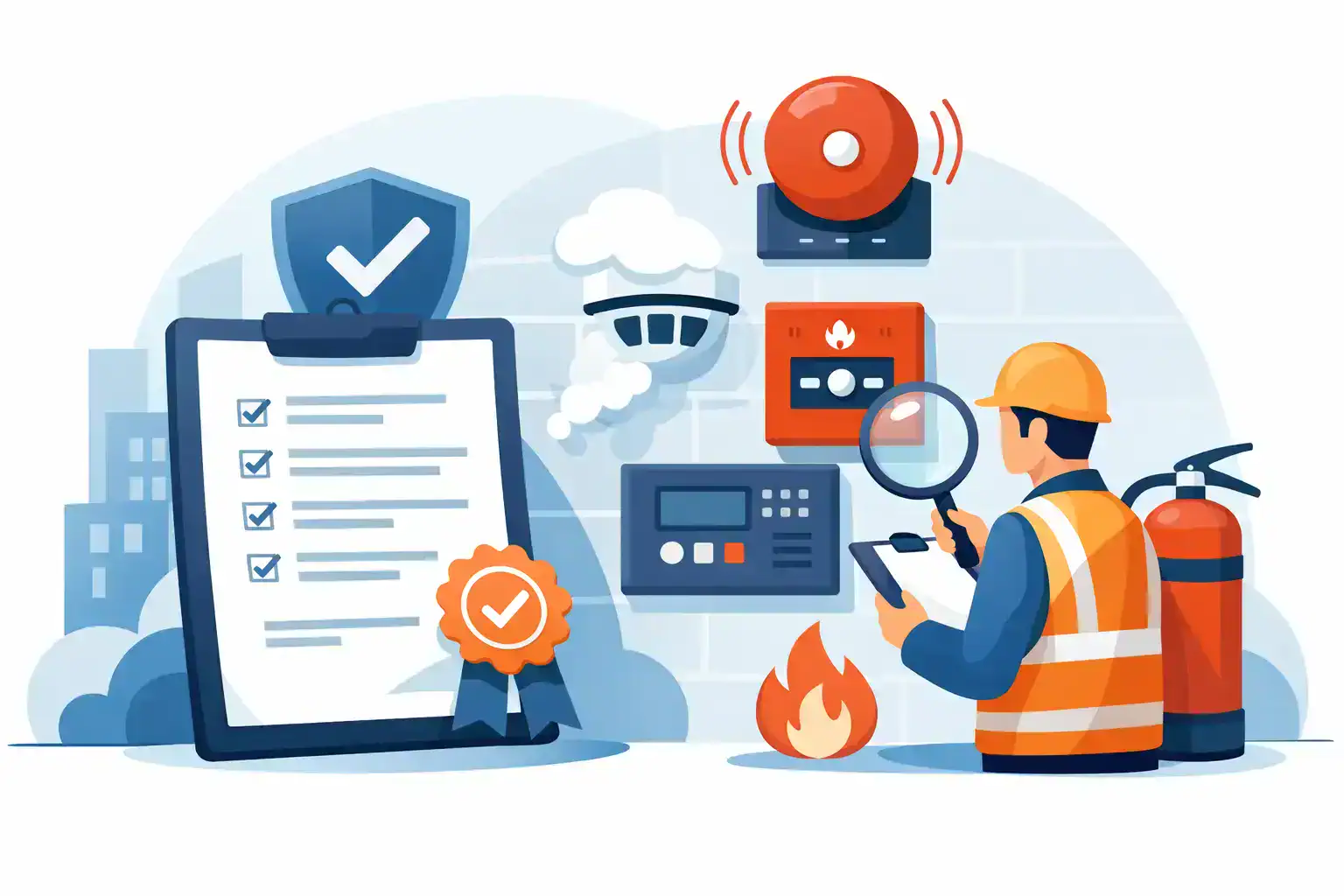
🔥 6. Fire Protection & Life Safety Engineering

This is our core specialty. All fire protection designs, reports, and approvals are delivered in strict compliance with SBC, NFPA, Saudi Civil Defense, and MODON regulations.

🔴 Firefighting Systems Design

  • Wet, Dry, Pre-Action & Deluge Sprinkler Systems
  • Foam systems, foam monitors & foam standpipes
  • Water Mist systems (NFPA / UL / FM)
  • Fire pump room & hydraulic calculations
  • ESFR, CMSA, CMDA & In-Rack Sprinklers

🔔 Fire Alarm & Detection Systems

  • Addressable, Conventional & Voice Evacuation
  • VESDA, Linear Heat & Video Smoke Detection
  • Smart & IoT-enabled fire detection systems

📄 Fire Safety Studies & Reports

  • Fire Strategy Reports
  • Fire Risk Assessments
  • CFD Smoke & Evacuation Analysis
  • SBC, NFPA & MODON compliance reports
  • Emergency & Evacuation Plans

🏭 7. Industrial Engineering Consulting

  • Factory layout & material flow optimization
  • Production line improvement & lean manufacturing
  • OEE, time & motion studies
  • Industrial piping & process engineering

🛢️ 8. Oil & Gas Engineering Consulting

  • API 650 & API 620 storage tank design
  • LPG, LNG & Natural Gas piping systems
  • Explosion risk & ATEX hazard studies

🌿 9. Environmental Engineering Consulting

  • Environmental Impact Assessments (EIA)
  • Air quality & emission monitoring
  • Waste & hazardous waste management
  • STP, WWTP & grey water systems

📞 Contact Us for Engineering Proposals

WhatsApp / Call: 0557984942

WhatsApp / Call: 0545587404

Email: project.manager@telal-elwatan.com

لقسم الاستشارات الهندسية والتقارير والشهادات ومتطلبات الدفاع المدنى والبلدية و هيئة مدن  يرجى الاتصال على 0557984942

للتوريدات والطلبات الاخرى يرجى ارسال طلبك واتس اب لخدمتكم

بشكل اسرع على احد الارقام التالية 0531433890 

X